
For many Ford owners and people who like to do things themselves, knowing how the wires are connected in a car’s stereo system is crucial for having great sound. Learning how to install a new stereo or fix an electrical issue with your Ford stereo helps ensure safety, efficient troubleshooting, and the ability to customize and upgrade your audio system.
It also allows users to optimize sound quality and save costs by preventing mistakes which also enhances the vehicle’s resale value. Furthermore, the knowledge empowers individuals to manage their car’s audio system effectively and enjoy a trouble-free driving experience. In this article, we’ll equip Ford owners with the knowledge needed to wire their car’s audio system without much hassle.
Ford Stereo Wiring Color Code
Proper connections help ensure that audio signals travel efficiently from the head unit to the speakers. This, in turn, results in clear and high-quality sound reproduction. Ford, like many other car manufacturers, adheres to specific wiring standards for its car stereo systems.
The wire codes are unique to Ford vehicles and they may differ slightly from those of other automakers. These standardized wire colors serve as a crucial guide to connecting various car stereo components correctly.
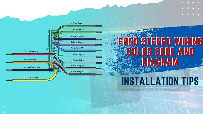
Below is a detailed list of Ford wire harness color codes and their corresponding functions;
- Red- The red wire typically represents the power source. This cable connects to the vehicle’s ignition switch to provide constant or switched power to the stereo system.
- Black- Black wire is usually designated for grounding. It helps ensure a safe electrical connection with the vehicle’s chassis to prevent electrical faults and ensure proper functioning.
- Yellow- Yellow wire is typically designed to connect to the battery’s positive terminal. This connection ensures that the stereo maintains its memory and settings even when the vehicle is turned off.
- Blue- The blue wire is used for remote turn-on. Its function is to enable the amplifier or other accessories to power up when the stereo is turned on.
- White- The white wire is typically associated with the front left speakers in the stereo system.
- White with black stripe- This wire is used as the negative wire for the front left speaker.
- Gray- Gray wires are usually connected to the front right speakers.
- Gray with black stripe- Similar to its counterpart for the left side, this wire serves as the negative connection for the front right speaker.
- Green- Green wires often connect to the rear left speakers.
- Green with black stripe- This wire is the negative connection for the rear left speaker.
- Purple- Purple wires are used for connecting to the rear right speakers.
- Purple with black stripe- Like other negative wires, this one is used as the negative connection for the rear right speaker.
- Orange- Orange wires may be used for illumination, which allows you to connect the vehicle’s dash lights to adjust the stereo’s brightness with the vehicle’s lighting.
- Orange with white stripe- This wire can be used for dimmer control, allowing the stereo’s display to adjust brightness in sync with the vehicle’s dimmer switch.
- Brown- Brown wires are sometimes used for phone mute or other accessory functions.
Ford Stereo Wiring Diagram
Understanding Ford’s Stereo wiring diagram is crucial for a successful audio system installation or modification. The diagram provides a visual representation of how various components are connected. However, always refer to the specific diagram provided for your Ford model and year to ensure accuracy and avoid wiring errors.
That said, here are some guidelines that can help you interpret Ford’s Stereo wiring diagrams;
- Key- Begin by locating the key, which typically appears on the diagram itself or in the accompanying documentation. This key explains the meaning of various symbols and color codes used in the diagram.
- Wire colors- Identify the wire colors on the diagram and cross-reference them with the Ford stereo wiring color code. This step ensures you are connecting the right wires to the correct components.
- Car stereo components- Recognize the symbols representing different audio system components, such as the head unit, speakers, amplifiers, and power sources. Common symbols include rectangles for head units, circles for speakers, and triangles for amplifiers.
- Connections- Pay attention to the lines or arrows connecting the symbols. These lines indicate how the wires are linked from one component to another. Solid lines typically represent primary electrical connections, while dashed lines may indicate secondary or optional connections.
- Labels and numbers- Look for labels or numbers next to the lines connecting components. These labels often correspond to pin numbers on connectors or specific terminals on components, which guides you on where to make the connections.
- Ground points- Ground connections are vital for safety and proper operation. Ground symbols usually resemble a series of short lines attached to a single point. Identify these symbols to ensure proper grounding.
- Multiple pages- Complex audio systems may require multiple pages of wiring diagrams. Ensure you follow the sequence and page references provided to understand the complete wiring configuration.
Examples of Ford Stereo Wiring Diagrams
2007 Ford Explorer Wiring Diagram

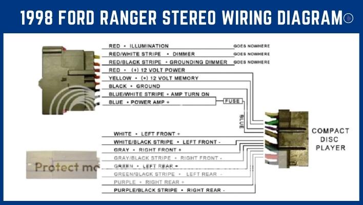
1998 Ford ranger stereo wiring diagram
Ford Stereo Installation Tips
- Safety first –Always disconnect the vehicle’s battery before working on the stereo wiring. This helps prevents electrical shocks and reduces the risk of short circuits.
- Use the right tools- Invest in quality crimping tools, wire strippers, and millimeters. This will help make wiring tasks more precise and reliable.
- Read the user manual- Consult your vehicle’s service manual and the documentation for any aftermarket components you’re installing. These manuals often provide specific information about wiring and connections.
- Check wire quality- Inspect the condition of existing wires. If you notice frayed, damaged, or corroded wires, replace them to ensure reliable connections.
- Label wires- When working on complex systems or if you need to pause your work, label wires with their corresponding functions or locations to avoid confusion.
- Plan your wiring route- Plan how you’ll route wires through the vehicle to minimize interference and potential damage. Avoid routing wires near hot or moving components.
- Secure wires properly- Use wire ties, clips, or loom tubing to secure wires in place. This helps prevent them from coming loose or rubbing against sharp edges, which can lead to damage or shorts.
- Soldering vs. crimping- While crimping connectors are commonly used, some prefer soldering for a more secure connection. However, soldering requires skill- if done incorrectly, it can damage wires or components.
- Fuse protection- Install appropriate fuses on power lines close to the battery to protect against electrical faults. Consult the manual or a professional for the correct fuse size.
- Grounding- Ensure that all ground wires are securely connected to clean, unpainted metal surfaces on the vehicle’s chassis. A poor ground connection can lead to electrical issues.
- Test connections- Before finalizing your installation, test connections for continuity and functionality. Use a multimeter to verify that wires are properly connected and that there are no shorts or open circuits. When making significant changes or upgrades, test your audio system in stages to identify and resolve issues early in the process.
Conclusion
Understanding the Ford stereo wiring color code is fundamental for anyone working on their car’s audio system. The Ford stereo wiring code and diagrams provided here serve as a valuable resource to navigate installations and troubleshoot common issues in Ford car stereo systems. Luckily, most Ford stereos are compatible with aftermarket wiring harnesses, making it easier to find an appropriate option for your vehicle. This helps ensure a smoother installation and reinforces the convenience of achieving your desired audio setup.